Network
Topology
Network
Topology defines as physical or logical layout of a network. It is the way different nodes are placed and
interconnected each other. Most of all
network topology gives a solid idea of how the data is transferred between
interconnected nodes.
In the
beginning there were simple computer networks. Most of the time requirement of
the computer network was to transfer user data in between to computers or
computer to server. But eventually when requirements are complicated need for
the more complex and sophisticated networks popped up. Most of the financial
companies, banks, government offices had a great deal of difficulties to
back-up their daily progress. With the evolution of network technology backing up valuable data
and restoring after critical failures such as natural disasters, cyber-attacks
and intellectual theft. Presently almost all companies store their valuable
data within their computers, servers and data centers. In banks they have their
own backup systems. As an example, when a customer withdraws or deposit money
through a ATM or Cash deposit machine his bank account automatically updates
necessary data same time through network. Also they have added security
features and filtering systems as a network feature. If you have With day to day
work stress most of the employees used to visit social media websites. In
centralized networks, network administrator can block unwanted traffic as face
book, twitter, Instagram in order to maintain productivity of the company.
Firewalls can be added to the server and easy maintain access control by
limited staff.
Networks
can be design and adapt to the shape and the original design of the building,
organizational structure and behavior. Some of the offices buildings require
star topologies and some of them can be manage by using mesh networks.
With
the evaluation of the network technologies, equipment and topological designs
most of the technological giants moved to fiber optic networks. These high
speed fiber networks carry more than 100 Gbps data rate without any delay in
between Local Area Networks as well as Wide Ares Networks across the globe.
Each
devices or computers connected to a single cable or backbone is called as bus
topology. Depending on the type of network card in each computer of the bus
topology, a coaxial cable or a RJ-45 network cable to connect computers
together.
Host of
the bus network called as Station or Workstation. In a bus network, each and
every station will receive all network traffic, and the traffic generated by
every station has equal transmission priority.
A bus network forms a single network segment and collision
domain. In order for nodes to transmit on the same bus
simultaneously, they use a media access control technology
such as carrier sense multiple
access (CSMA).
Advantages and disadvantages of the BUS topology
|
Advantages
|
Disadvantages
|
|
·
Easy to implement
|
Network
disruption when computers are added or removed
|
|
·
Not use any specialized equipment
|
A
break in the main cable will prevent all systems from accessing the network.
|
|
·
No need technician knowledge to implement
|
Difficult
to troubleshoot.
|
|
·
Require less cable.
|
Low
security
|
|
·
Easy to connect computers
|
Limited
cable length and number of stations.
|
|
·
Less expensive
|
|
|
·
If one node fail, other nodes are not
effected
|
|
It is
the most common Centralized network topology in use. In this configuration,
every node connects to a central network device, like
a hub, switch, or computer. The central network device acts as
a server and the peripheral devices act as clients. Depending on
the type of network card used in each computer of the star topology,
a coaxial cable or a RJ-45 network cable is used to connect
computers together.
There are two types of Star
Topology
Extended
Star Topology
The
network based upon the physical star topology has one or more repeaters between
the central node and the peripheral or spoke nodes. The repeaters being used to
extend the standard maximum transmission distance between the central node and
the peripheral nodes.
Distributed
Star Topology
These
networks are individual networks that are based upon the physical star topology
connected together in a liner fashion with no central or top level
connectivity.
Advantages and disadvantages of the STAR topology
|
Advantages
|
Disadvantages
|
|
·
easily expended
without disruption to the network
|
·
The centralized device increase overall cost
of the network
|
|
·
cable failure
affects only a single user
|
·
The nodes depend on capacity of central
devise.
|
|
·
Centralized management.
|
·
requires more cables
|
|
·
Failure of one node or link doesn’t effect
the rest of the network.
|
|
|
·
easy to troubleshoot and isolate problems
|
|
|
·
gives better
performance than BUS topology.
|
|
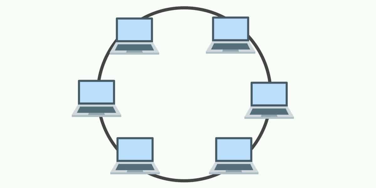
In this
types of networks each node connected to two other nodes of the network, with
two connections forming a double ring. First and last node is connected to each
other with two connections. Normally only one ring is active and caring date in
to a single direction unless there is a failure or breakdown in active ring,
data transmission will switch to protection ring and start transmitting to
opposite direction.
Advantages and disadvantages of the RING topology
|
Advantages
|
Disadvantages
|
|
·
cable faults are
easily located , making troubleshooting easier
|
·
expansion to the
network can cause network disruption
|
|
·
ring network are
moderately easy to install
|
·
a single break in
the cable can disrupt the entire network.
|
|
·
Each computer from the network as equal access
to resources.
|
·
In a packet pass to the computers its make
slower than the star topology.
|
|
·
With lord of the network increases it can
give a better performance than bus topology.
|
·
When node goes down, entire network get
effected.
|
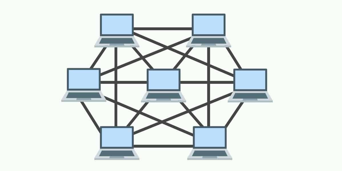
Network
topology in which a node transmits its own data as well as serves as a relay
for other nodes. Best and most efficient path for effective communication is
provided by routers. In the event of hardware failure many routes are available
to switch back and continue the network communication process.
There
are two types of MESH Network topologies.
Full
Mesh networks
This
topology is active when each node of the network is connected to all other
nodes with direct connections. This provides greater redundancy because if a
node goes down, network traffic can be routed through other nodes. Each node
accesses the neighboring business nodes and finds the best path for efficient
and reliable communication.
Partial
Mesh Networks
Partial
Mesh Network topology is active when some nodes are connected to all other
nodes via direct connections, while others are connected to only one or two
nodes. This is less expensive than the entire mesh topology but has less
redundancy.
Advantages and disadvantages of the MESH topology
|
Advantages
|
Disadvantages
|
|
·
provide redundant
path between devices
|
·
chances of redundancy in many of the network
connection.
|
|
·
the network can be
expended without disruption to current uses
|
·
complicated
implementation
|
|
·
data can be transmitted from different
devises simultaneously.
|
·
cable cost is high
|
|
·
If one of the components fail, there is also
alternative path to continue.
|
·
The setup and maintainers is very much complicated
and difficult.
|
5. Tree Network Topology
Tree
network is a combination of two or more star networks connected together. Each
star network is a Local Area Network (LAN) and it has a central computer server
which all nodes are directly connected. The servers of the star networks are
connected to a main cable called the bus. Tree networks are a BUS Network of
STAR Networks.
Advantages and disadvantages of the TREE topology
|
Advantages
|
Disadvantages
|
|
·
The expansion of network possible and easy
|
·
Maintains process is more hard
|
|
·
Error detection and correction process is
easy
|
·
The main
cable(back bone cable) break whole network goes break down.
|
|
·
If one segment is damage other segment are
not affected.
|
|